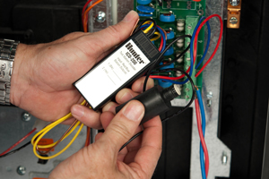
Line Fault: This display indicates a power or wiring related problem. Generally it will appear if an IDS or VSX controller has detected an Overload condition (transformer current draw in excess of 2 amps), and no stations were scheduled to be running. If there were no stations running but a 2 + amp current was sensed, this would indicate a direct short circuit in the two wire path, or a potential transformer problem.
To test one of the main component behind the two wire path's power supply (Decoder Output Board), follow these steps:
|
1. Remove the two wire path from the Decoder Output Board. 2. Place the red and blue wires from a known working decoder(preferably new) onto the terminals the two wire path was disconnected from. 3. Try to run the connected decoders established station number. If the decoder has not been assigned a station number you will have to program one before this procedure will work. 4. With a working solenoid connected to the decoder(and the station running) you should get a click out of the solenoid as it is now engaged and activated. If the solenoid does not click and the controller's display shows the station running, assuming the decoder was assigned to the proper station; the Decoder Output Board or upper Transmitter Board has taken a direct strike and needs to be replaced. |
|
As an additional note the upper Transmitter Board is responsible for converting the consistent 32V AC to a fluctuating AC current that ranges from 22V to 78V. These fluctuations in current provide the decoder path the language needed to communicate commands to and from the controller to the decoder.
Additional Decoder Output Board Testing:
| 1. Identify the Transmitter Board in your IDS controller. It is the board in the top right with the Power Supply Board piggy backed on top of it. |  |
| 2. With a volt meter put a single probe on each side(flat head screws) of the lower wire harness. The transformer feeds this board directly with a consistent 32V of AC current. Be sure that the Transmitter Board is receiving the necessary voltage from the transformer. |  |
| 3. Next, put the same testing probes on a pair of Decoder Wire Path terminals(flat head screws) and see that voltage is making it's way through the Decoder Output Board. If there is a fluctuating voltage ranging from 22V to 80V then the Transmitter Board and Decoder Output Board are still in a working capacity. |  |
Still need help? We're here.
Tell us what you need support with and we'll find the best solution for you.

