In this Article
- Mounting
- Wiring
- Operation Check
- Adjustments and Operation
- Bypassing the Sensor
- Troubleshooting
The Rain-Clik you have just purchased provides a new level of performance, water savings and installation convenience never before seen in an economical rain sensor package.
|  |
MountingFind a spot that will receive unobstructed rainfall and choose your desired mounting option. Once the sensor is fully assembled, proceed to the mounting location. Following are some tips and guidelines for completing each mounting option.
Wall Mount Mounting Instructions
Gutter Mount Mounting Instructions
Conduit Mount Mounting Instructions
Helpful Hints for Mounting
Once the Rain-Clik is mounted, run the wire to the controller, and fasten it every few feet with wire clips or staples for best results. If an extension to the wire provided is needed, use the following table to determine the minimum wire gauge needed:
|
WiringSRCThe Rain-Clik connects directly to the SRC. This allows you to easily override the sensor by using the RUN (BYPASS SENSOR) position on the dial.
|
|
XC, EC, X-Core, ICC and Pro-CThe Rain-Clik connects directly to the ICC or Pro-C. This allows you to easily override the sensor by using the Sensor switch on the front panel.
|
|
Other ControllersThe two most common situations are shown below.
|
|
Operation Check to Verify Correct WiringTurn on one zone of the irrigation system that is visible while you are in reach of the Rain-Clik. Manually depress the spindle at the top of the Rain-Clik until you hear the switch “click” off. The sprinkler zone should stop instantaneously. If it does not, check wiring for correctness. It is not necessary to “wet” test the Rain-Clik, although it will test the operation fine, if desired. (See Figure 5) |
|
Adjustments and Operation
The Rain-Clik can keep the irrigation system from starting or continuing after rainfall.
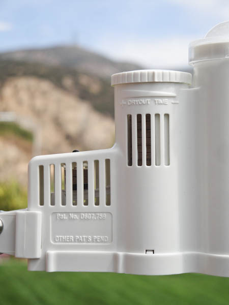
The time that it takes the Rain-Clik to reset for normal sprinkler operation after the rain has stopped is determined by weather conditions (wind, sunlight, humidity, etc.) These conditions will determine how fast the hygroscopic discs dry out, and since the turf is also experiencing the same conditions, their respective drying rates will roughly parallel each other. So when the turf needs more water, the Rain-Clik is already reset to allow the sprinkler system to go at the next scheduled cycle.
The Rain-Clik utilizes a single disc technology to turn off your sprinkler system within the first five minutes of the rain falling. For light showers and amounts of rain less than 1/8", the single disc will shut off the system for 30 minutes to 4 hours, depending on weather conditions. Adjusting the vent cap will not have an effect on the dryout time of the single disc. For heavier rain showers in excess of 1/8", the disc stack under the vent cap will hold the system off for an appropriate amount of time. The disc stack dryout time is what the vent cap adjustment controls.
Bypassing the Sensor
The Hunter ICC, Pro-C and SRC controllers are equipped with a built-in bypass that allows you to override an active sensor. For controllers not equipped with this feature, should you desire to bypass the operation of the Rain-Clik for any reason (i.e., turn on your system even though the Rain-Clik has shut “off” due to rainfall), there is a simple way to do this – add our Bypass Switch Box. This mounts on or next to the controller, and by simply moving the switch, the Rain-Clik is bypassed.
Note: Using the “manual” switch on non-Hunter controllers typically will not bypass the sensor.
Troubleshooting
Follow these simple checks first before assuming the unit is bad and replacing it.
System will not come on at all:
- First, check to see that the Rain-Clik discs are dry and the switch “clicks” on and off freely by pressing the top of the spindle.
- Next, look for breaks in the wire leading to the Rain-Clik and check all wire junctions.
- Finally, if the Rain-Clik is dry and the wire leading to it is good, check the Rain-Clik switch by nicking the insulation of the two “outer” wires near the unit to expose copper. Turn one sprinkler zone on, and apply a “jumper wire” across the two exposed wires. If the sprinkler now comes on, the switch is bad. Wrap all nicked wires with electrical tape.
System will not shut off even after heavy rainfall:
- Check wiring for correctness (see “Operation Check to Verify Correct Wiring”).
- Is the rainfall actually hitting the Rain-Clik? Check for obstructions to rainfall such as overhangs, trees or walls.
Manufactured under U.S. Patent Pending
All Rain-Clik™ models are listed by Underwriters Laboratories, Inc. (UL). Samples of these devices have been evaluated by UL and meet the applicable UL standards for safety.
Still need help? We're here.
Tell us what you need support with and we'll find the best solution for you.