LCD Display
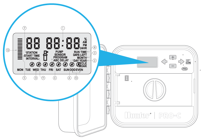
- Main Display: Indicates various times, values, and programmed information
- Year: Identifies current calendar year
- Month: Identifies current calendar month
- Day: Identifies current calendar day
- Start Time: Identifies selected program start time
- Program Selector: Identifies the program in use: A, B, or C
- Station Number: Identifies currently selected station number
- Run Time: Allows user to set each valve station run time from 1 minute to 4 hours
- Days of the Week: Identifies days of the week to water or not water
- Odd/Even Watering: Identifies if odd or even watering days are selected
- Interval: Identifies if interval watering has been selected
- Seasonal Adjustment: Displays in increments of 5%, the percentage of seasonal adjust that has been selected
![]() Running: Sprinkler icon indicates when watering is occurring
Running: Sprinkler icon indicates when watering is occurring
![]() Rain Drop: Indicates watering will occur on selected day
Rain Drop: Indicates watering will occur on selected day
![]() Crossed Rain Drop: Indicates watering will NOT occur on selected day
Crossed Rain Drop: Indicates watering will NOT occur on selected day
Control Buttons and Switches
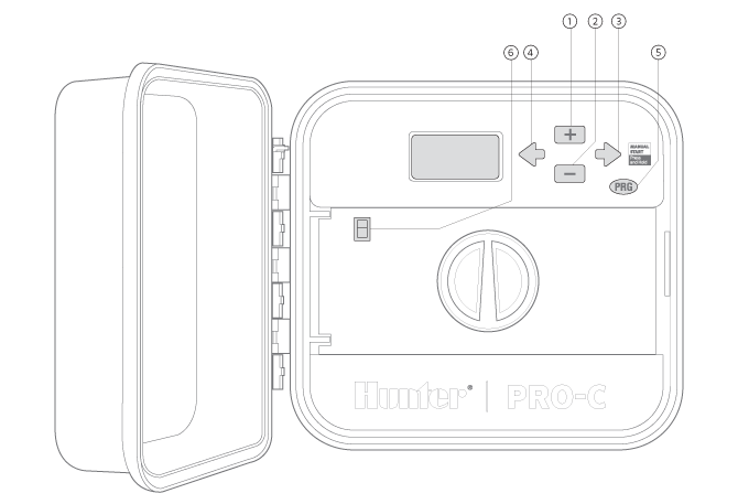
- Increases the selected flashing display
- Decreases the selected flashing display
- Advances the selected flashing display to the next item, also use to start a manual cycle
- Returns selected flashing display to the previous item
- Selects programs A, B, and C; also to start a test program
- Rain Sensor Bypass: SwitchUse to bypass weather “Clik-type” sensors if one is installed
Control Dial
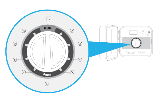
- Run: Normal dial position for automatic operation
- Set Current Date/Time: Set current date and time
- Set Program Start Times: Set 1 to 4 start times in each program
- Set Station/Run Times: Set each station run time
- Set Days to Water: Select individual days to water, odd, even or interval watering schedule
- Set Pump Operation: Turn pump or master valve on or off for each station
- Seasonal Adjustment: Make global run time changes without programming the controller (from 5% to 300%)
- Solar Sync®: Allows user to program settings when using Solar Sync ET sensor
- Manual-Single Station: Activates a one time watering of a single station
- System Off: Used to discontinue all programs and stop all watering until the dial is returned to the RUN position, or to set the programmable rain off feature
Wiring Compartment
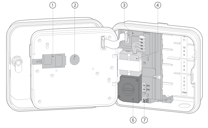
- 9-Volt Battery: An alkaline battery (not included) allows programming of the controller without AC power
- Reset Button: This button will reset the controller. All programmed data will remain intact
- Power Area: Used to attach transformer, sensor wires, and other systems to the controller
- SmartPort® Input Terminals: Used to connect a SmartPort, which enables Hunter remote controls
- Transformer: A transformer is installed (Outdoor models only, indoor models are supplied with a plug-in transformer)
- Junction Box: This box provides an area for connecting primary AC power (Outdoor models only)
- Ground Lug: For additional surge protection, connect lug to earth ground
- Sensor Terminals: Used to connect Hunter Solar Sync or “Clik-type” sensors
- Power Slide:Release to remove or insert Pro-C modules