The PSR-B was developed to provide a solution for irrigation controller and pump start relays installations that have insufficient power to energize the pump relay. A common cause for this problem is the use of too small a wire size for the distance from controller to the pump start relay. The PSR-B allows the operation of the pump start relay through the PSR-B relay, which requires only a small amount of current draw. For correct wire sizing where the PRS-B is not required, please click on the following link: PSR Wiring Chart.
NOTE: Connecting the Pump Start Relay Booster should only be done by a licensed electrician following local codes. Improper installation could result in shock or fire hazard.

- Select a location that is convenient to a power source.
- Make sure to abide by all electrical codes when attached to an external wall.
- Place the PSR-B against the wall and align the keyhole (B) on the back of the unit. Mark the spot as well as the two holes (C) at the bottom of the cabinet.
- Drill a 6mm or 15/64" hole at each spot.
- Install screw anchors (A) into the holes if attaching the PSR-B to drywall, masonry, or plaster walls.
- Holding the PSR-B, line up the holes and drive screws into anchors to securely fasten it to the wall.

- Remove the screws and cover from the internal junction box.
- For all connections, route the AC wires through the 1/2" conduit opening inside the junction box.
- For 120 VAC connections, twist the VAC wires together as shown in Figure 1 (The Brown wire is not used). For 230 VAC operation, connect the incoming power wire (HOT) to the brown wire lead from the transformer (The Black wire is not used). Use wire nuts supplied to secure the connections.
- Replace the junction cover.
NOTE: Be sure to install a wire nut on the unused brown or black wire.

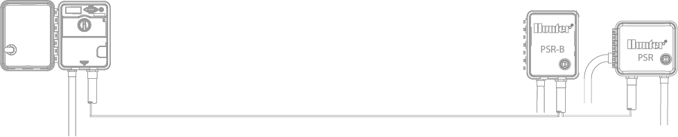
- Route one RED wire to P/MV terminal on your irrigation controller, and the other RED wire to the common terminal.
- Route the two YELLOW wires to each of the PSR 24VAC wires using minimum 18G wire.
Brauchen Sie noch weitere Unterstützung? Wir stehen Ihnen jederzeit zur Seite.
Teilen Sie uns mit, in welchem Bereich Sie Unterstützung benötigen, und wir finden die beste Lösung für Sie.