The Pro-C is compatible with the Hunter Solar Sync. Solar Sync is a sensor system that will automatically adjust the Pro-C controller’s watering run times (based on changes in local climate condition) by using the Seasonal Adjust function. The Solar Sync uses a solar and temperature sensor to determine evapotranspiration (ET), or the rate at which plants and turf use water, and also includes Hunter Rain Clik and Freeze Clik technology that will shut down irrigation when it rains and/or during freezing conditions.
The Pro-C / PCC (blue panel and blue buttons) with the SOLAR SYNC dial position is programmed with the Solar Sync technology and, therefore, does not require the use the Solar Sync module.
The older style Pro-C controllers (green buttons) require the installation of the Solar Sync module as well as the Sensor.

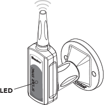
Connect the Green and Black wire from the Wireless Solar Sync Receiver directly to the “SEN” terminals on the Pro-C 400 controller as shown on image to the right. It does not matter which wire connects to which terminal. The Solar Sync Receiver can be mounted on the side of the Pro-C controller using an available knock out and secured with the supplied conduit nut. Or, use the supplied bracket to mount the Wireless Receiver on the wall next to controller. Depending on the installation, the supplied 1.5" (3.8cm) extender may be required. Route the wires from the Wireless Receiver into the controller cabinet.
Turn the dial to the SOLAR SYNC position. The display will initially show dashed lines and then will show the default Region setting (3) on the left and the default Water Adjustment setting (5) on the right.
Adjust the Region by using the up or down arrows. Press the right arrow once, the Water Adjustment will be flashing. Adjust the Water Adjustment by using the up or down arrows
NOTE: Older model Pro-C controllers (green buttons) will require the installation of the Solar Sync module as well as the Solar Sync Receiver.

Begin by activating the CR2032 backup battery (used for date/time backup in the event of a power outage) by pulling the battery insulator at the bottom of the module. The expected battery life is ten years. If the battery requires replacement, the battery compartment is located on the back of the Solar Sync module. Remove the cover and install the battery with the positive side (+) of the battery visible, facing toward you. Replace the battery cover. Replace battery with CR2032 type battery only. Use of another battery may present a risk of fire or explosion.
NOTE: Battery may explode if mistreated. Do not recharge, disassemble or dispose of in fire.

The Solar Sync module is designed to be wall-mounted next to the irrigation controller. A rubber cover is provided for outdoor installations to protect the module from the weather. Use two anchors or self-tapping screws to secure the module to the wall. Place the rubber cover mounting tab behind the module before screwing the module to the wall.
NOTE: If you are installing Solar Sync on an ACC or X-Core Controller, the Solar Sync Module is not required. For the ACC or X-Core controllers, the WSSSEN kit should be used, as it does not include the Module. (See the controller‘s owner‘s manual for more details.)
MODULE
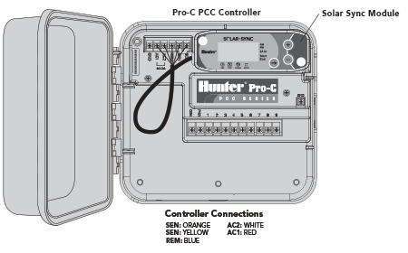
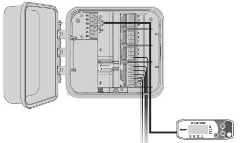
The PCC series version of the Pro-C is designed so that the Solar Sync module can be installed inside the controller cabinet. Use the two screws provided to mount the module as shown in the diagram.
NOTE: For Pro-C PCC Series controllers, there are provisions inside the controller to mount the Solar Sync module.
- Connect the red wire from the Solar Sync module to the AC1 terminal
- Connect the white wire from the Solar Sync module to the AC2 terminal
- Connect the blue wire from the Solar Sync module to the REM terminal
- Remove the flat metal jumper from the two SEN terminals
- Connect the yellow wire to one of the SEN terminals
- Connect the orange wire to the other SEN terminal
WIRELESS RECEIVER
Mount the Wireless Receiver on the controller cabinet using an available knock out and secure with the supplied conduit nut. Or, use the supplied brackets to mount the Wireless Receiver on the wall. Depending on the installation, the supplied 1.5" (3.8 cm) extender may be required (shown below). Route the wires from the Wireless Receiver into the controller cabinet.
- Make sure power to the controller is turned off
- Connect the black Receiver wire to the black Module wire
- Connect the green Receiver wire to the green Module wire
- Initialize communication by following steps outlined in “Addressing Wireless Receiver/Sensor” section
MODULE
For the PC series Pro-C Modular controller, mount the Solar Sync module on the wall next to the controller cabinet. There is an additional knockout on the right side of the controller cabinet to route Solar Sync wires into and out of the cabinet.
- Connect the red wire from the Solar Sync module to the AC1 terminal
- Connect the white wire from the Solar Sync module to the AC2 terminal
- Connect the blue wire from the Solar Sync module to the REM terminal
- Remove the flat metal jumper from the two SEN terminals
- Connect the yellow wire to one of the SEN terminals
- Connect the orange wire to the other SEN terminal
WIRELESS RECEIVER
Mount the Wireless Receiver on the controller cabinet using the options described for the PCC Series. Due to the position of the power module in the Pro-C controller, a more convenient option may be to mount the Wireless Receiver to the wall using the Wall Mount Bracket.
- Make sure power to the controller is turned off
- Connect the black Receiver wire to the black Module wire
- Connect the green Receiver wire to the green Module wire
- Initialize communication by following steps outlined in "Addressing Wireless Receiver/Sensor" section
To initialize communication manually between wireless Receiver and Sensor:
- After Receiver’s green and black wires have been connected (see “Connecting To The Controller” section), restore power to the controller
- The red LED in the center of the wireless Receiver will turn on and stay solid for 10 seconds, indicating that it is in search mode, searching for a signal from a wireless sensor
- While the red LED is solid and the wireless Receiver is in search mode, press and hold the spindle on the wireless Sensor. The LED on the wireless Receiver will blink 4 times and then turn off, indicating that the signal from the wireless Sensor has been acknowledged.
To Validate Receiver/Sensor Communication or Re-address:
- Press and hold the spindle on the wireless Sensor
- The LED on the wireless Receiver will blink 2 times, confirming that the Receiver is addressed to the Sensor properly
NOTE: In the event of a power outage (or any other reason when the Receiver loses radio contact with the wireless Sensor) the Receiver will automatically go into search mode to re-establish communication with the Sensor once power is restored. However, when power is restored the controller will automatically go into rain shut off mode until communication with the Sensor is re-established, which may be up to 60 minutes (maximum). Performing the steps listed above to validate Receiver/Sensor communication will remove the controller from rain shut off mode and will return to its programmed irrigation schedule.
The Solar Sync is simple to program. Only a few initial steps are necessary to program the module. When power is initially turned on, the display will show the time of day. Pressing the button will sequence through the programming functions on the module. An arrow along the bottom of the display will indicate the function being programmed.

Current Time
Press the button press until the arrow is displayed over the clock icon. The time of day will be flashing. Use the or button to set the current time. The arrow to the right of the display indicates AM or PM.
Note: 24 hour mode will only be enabled with a 50 Hz power input.

Controller Type
Press the button until the arrow is displayed over the controller icon. Use the or button to select the correct Hunter controller.
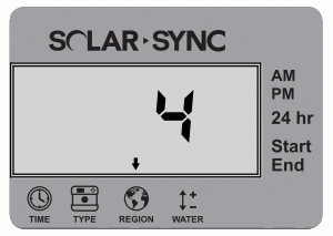
Region
For accurate measurements, the Solar Sync module needs to be programmed for the typical ET (average July ET) for your region. Press the button until the arrow is displayed over the globe icon. Use the or button to select your region (regions 1 through 4).

Watering Adjustment
If you find that your landscape is "wetter" or "drier" than it should be, a watering adjustment function is provided to adjust watering equally to all stations. Use the button until the arrow is displayed over the water icon icon. Use the or button to increase or decrease the amount of watering scaled 1 to 10 (1 for less water and 10 for more water). Hunter recommends observing performance carefully over the first weeks of operation before adjusting the watering.

NOTE: The Solar Sync module offers a “No Water Window” that prevents any irrigation from occurring during a specific period of the day. The “No Water Window” is a hidden feature on the module. Press and hold the right arrow button for 5 seconds to program the "No Water Window."
A right arrow will be flashing at the START along the right side of the display. Use the or buttons to adjust the time you would like the no watering period to start. Pressing the button again will display an arrow flashing at END. Use the or buttons to adjust the time you would like the no watering period to end.
Still need help? We're here.
Tell us what you need support with and we'll find the best solution for you.