Rain shutoff and other sensors must be setup in the Devices menu. We tell the controller what sensors are connected, and in some cases we set the response for each sensor.
Clik Sensors
Dial to the Devices menu, and select Clik Sensors for basic Hunter Clik sensors.

To set up a sensor, click the box for Enable Clik Sensor Input.
The ACC2 sensor inputs are already configured as Normally Closed, but this can be changed for other types of contactclosure sensor inputs to Normally Open.
It is also possible to enter a name for individual sensors.
Sensor location can be changed from Controller (corresponding to the terminals on the Power Supply Board), to any decoder output module, if the sensor is connected to an ICD-SEN sensor decoder. Choose the decoder output module to which it will be connected, and then select the Sensor Decoder address and port.
Sensor Response
Located on the Devices menu, Sensor Response sets which sensors will shut off which programs, in basic operations.
The sensor responses are set up for each program, one page at a time. If you want the same responses for multiple programs, set up the responses for the first program, then click the Copy soft key. You can then change the program number and click the Paste soft key to duplicate the settings.

There are three standard Clik sensor inputs on the Power Supply Board. If a Hunter Solar Sync sensor has been configured, there are also settings for Solar Sync Rain and Freeze.
Ignore: This means the program does not respond to the sensor.
Suspend (recommended): This means the program suspends watering when sensor is active (alarmed) but keeps track of time. If the sensor returns to normal, the suspended program will resume irrigating where it should be at that time in the schedule. The program will end when it was originally scheduled to end.
Pause (use caution): This means that the program stops where it is when the sensor is active. If the sensor returns to normal, the program will resume watering where it left off, causing the program to end later than originally scheduled.
It is not possible for a program to be set to both Pause and Suspend for different sensors, because they cannot both be active at the same time. If you change a response setting for a sensor, and another sensor for the same program changes automatically, this is not a bug.

Rain Delay: In the Sensor Response menu, press the soft key for Rain Delay. This optional setting will cause watering to stay off for a set number of days, after the sensor activation is over. Select the number of days for watering to stay off for each Clik sensor input.
Solar Sync
After connecting a Solar Sync sensor to the controller, set up operation in the Devices, Solar Sync menu.
- Check the box to Enable Solar Sync.
- Choose the Region and set the Water Adjustment, according to the Solar Sync manual instructions.
- For normal operations, this is all that is necessary. It will take the Solar Sync two or three days to register enough climate data to begin adjusting.

Solar Sync Delay allows a number of days to wait before automatic Solar Sync adjustment goes into effect (to establish new landscape, for example). Enter a number of days (1–250) to wait, and specify the Adjustment During Delay percentage to use during the delay period. At the end of the delay, the Solar Sync will begin adjusting automatically for the current climate conditions.
The delay does not interfere with the Solar Sync Rain and Temp functions. They will be operational during the delay.
Complete the setup by setting the programs to use Solar Sync in the Program, Seasonal Adjust menu.
Flow Sensors
To connect one or more flow sensors, set up operation in the Devices, Flow Sensors menu.
Select the sensor input number (1–6) to be set up. The controller has three Flow Sensor inputs built in, but three more can be added with the A2C-F3 Flow Expansion module.
ACC2 Decoder versions may also read flow via the two-wire path when flow sensors are connected to ICD-SEN sensor decoders. Use the Location window to select Controller (corresponding to one of the Flow terminals on the Power Supply Board or A2C-F3 flow expansion modules), or to select the decoder output module to which the flow sensor will be connected.
Specify the address of the sensor decoder for the flow sensor. Flow sensors may only be connected to Port "A" of a sensor decoder.
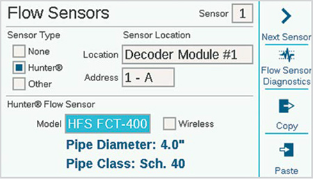
Check the box for either "Hunter" or "Other" flow meters.
If Hunter is checked, move to the Model field and select the Hunter FCT model number for the diameter of the pipe. This is all that is necessary to calibrate the setup.
"Wireless" is only checked for use with the Hunter WFS (wireless flow sensor), which requires a receiver installed at the controller.
If Other is checked, you must select the Flow Sensor Style and enter the calibration information. Some use K-factor and Offset, and others are Pulse type. Consult the flow meter supplier's documentation for the correct settings or contact Hunter Technical Support for additional information.
K-Factor and Offset: Obtain these values from the flow sensor manual, and enter here.
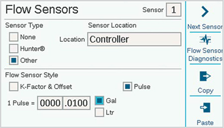
Pulse type: Enter the amount equal to a single pulse.
Enter the information for each flow sensor that is connected to a flow terminal. There are copy and paste soft keys available, if all the meters are the same type and size.
Once this information is entered for each flow sensor input, the controller is ready to read flow. However, each flow sensor must be attached to a Flow Zone (Flow, Flow Zones) before real time monitoring can occur.
Flow Totals may be viewed at the Flow menu.
Current flow rates (by sensor) can be read from the Home/ Activity screen with the View Flow soft key.
Flow Monitoring: Additional setup for station level flow monitoring is required in the Flow menu (Flow Zones), and in the Stations, Station Setup menu.
Still need help? We're here.
Tell us what you need support with and we'll find the best solution for you.