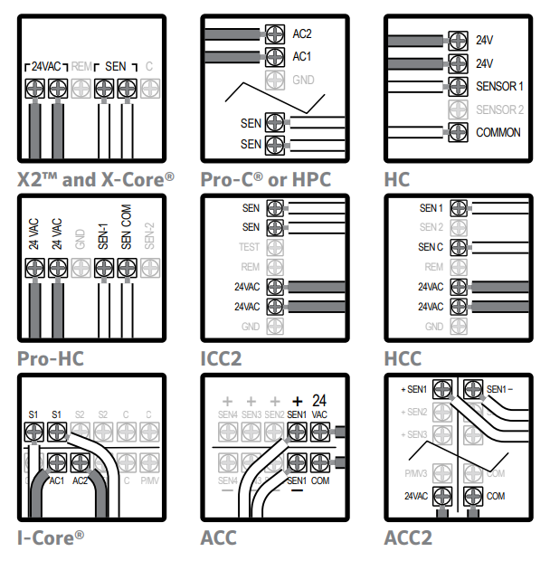
Wireless Rain-Clik™ - Installation Instructions

X-Core Controller

The Rain-Clik connects directly to the X-Core or XC. This allows you to easily override the sensor by using the Sensor switch on the front panel.

  1. Remove the sensor jumper across the two SEN terminals in the controller.
  2. Attach the two yellow wires to the 24 VAC terminals.
  3. Attach the blue wire to one SEN terminal and the white wire to the other SEN terminal.
  4. The orange wire is not used for installation on Hunter controllers.


Pro-C Controller PC400 (2014 or newer)
 
  1. Remove the sensor jumper across the two SEN terminals in the controller.
  2. Attach the two yellow wires to the 24 VAC terminals.
  3. Attach the blue wire to one SEN terminal and the white wire to the other SEN terminal.
  4. The orange wire is not used for installation on Hunter controllers.

Rain-Click Connecting to Pro-C Controller PC400


Pro-C Controller PC300 (Older than 2014)
 
  1. Remove the sensor jumper across the two SEN terminals in the controller.
  2. Attach the two yellow wires to the 24 VAC terminals.
  3. Attach the blue wire to one SEN terminal and the white wire to the other SEN terminal.
  4. The orange wire is not used for installation on Hunter controllers.


ICore Controller
 
  1. Remove the sensor jumper wire across the two SEN terminals in the controller.
  2. Attach the two yellow wires to the 24 VAC terminals.
  3. Attach the blue wire to one SEN terminal and the white wire to the other SEN terminal.
  4. The orange wire is not used for installation on Hunter controllers.

HC Controller
 
  1. Connect one sensor wire to sensor COMMON on the controller.
  2. Connect the opposite Normally Closed wire from the sensor to SENSOR1 or SENSOR2 on the controller.
  3. Configure in the Hydrawise app. Click here for help configuring a sensor.
  4. The orange wire is not used for installation on Hunter controllers.

Pro-HC Controller
 
  1. Connect one sensor wire to sensor COMMON (SEN-COM) on the controller.
  2. Connect the opposite Normally Closed wire from the sensor to SEN-1 or SEN-2 on the controller.
  3. Configure in the Hydrawise app. Click here for help configuring a sensor.
  4. The orange wire is not used for installation on Hunter controllers.

ACC2 Controller
  1. Connect the blue and white wire to any of the four Sensor Terminal pairs (SEN1 shown).
  2. Attach yellow wires to 24 VAC and COM terminals.
  3. Use features at the “Set Sensor Operation” dial position on ACC to complete the setup.
  4. Use Devices and Sensor Response options on ACC2 to complete the setup.
  5. See ACC/ACC2 owner’s manuals for further details.

Wiring the Receiver to Other Controllers: Normally Closed Sensor Applications

  1. Attach the two yellow wires to the 24 VAC  terminals.
  2. Attach the blue and white wire to the sensor terminals (if available) or in-line with the valve common  wire.

Reference Illustration

  1. Common wire to all valves
  2. Used for normally open sensor applications

Normally Open Sensor Applications

A few controllers on the market require normally open rain sensors. To attach the receiver to this type of controller, attach the blue and orange wire to the sensor input.

Controllers with 24 VAC Solenoids and a  Booster Pump

  1. Locate the common wire to the solenoid valves and the common wire to the pump relay. If these two wires are connected to the "common" terminal on the controller, disconnect both of them.
  2. Twist together these wires along with one of the wires from the Wireless Rain-Clik and secure with a wire nut.
  3. Attach the other wire from the Wireless  Rain-Clik receiver to the "common" terminal on the controller.

Reference Illustration

  1. Line-in
  2. Normally-open relay
  3. Line-out (to pump)
  4. Common wire to all valves
  5. Solenoid valves

Note: The pump circuit output must be 24 VAC. Do not proceed if 115 VAC.

SRC Controller (Discontinued)

  1. Attach the two yellow wires to the AC terminals of the SRC (polarity does not matter).
  2. Attach the blue wire to the RS terminal.
  3. Attach the white wire to the “C” terminal.
  4. Attach the valve common wire to the RS terminal.

Reference Illustration

  1. Common wire to all valves
  2. Used for normally open sensor applications. Hunter controllers use normally closed sensor wiring

Still need help? We're here.

Tell us what you need support with and we'll find the best solution for you.

Contact Support