|
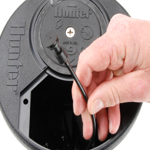
In hydraulic installations, the flange compartment should be used to make the Control Tubing connections to the rotor. This allows for tubing connections, pressure tests and flushing of the control lines - all without digging.
Converting C.O.M. models to the Hydraulic configuration – Remove the two stainless steel screws and lift the flange compartment lid to expose the flange compartment. Find the end of the ⅛ inch tubing that comes into the flange compartment from the bottom of the rotor (fig 1). Check-O-Matic (“C”) versions of TTS rotors can be converted for use in Normally Open Hydraulic systems by removing the end cap on the ⅛ inch tubing. To do so, slide the ¼ inch tube retainer towards the end of the tube (fig 2). Then, pull to remove the end cap with attached ¼ inch tube retainer from the brass connector fitting (fig 3).
To connect the ¼ inch control tube from the controller to the TTS rotor tubing, insert ¼ inch tubing from controller into the bottom of the flange compartment. Next slide the ¼ inch tube retainer (from end cap supplied with rotor) onto the ¼ inch Control Tubing. Then connect the ¼ inch Control Tubing to the rotor’s ⅛ inch Control Tubing by pressing together at the brass fitting. Finally, slide the ¼ inch tube retainer towards the brass fitting to lock the tube in place. |
fig 1
fig 2
fig 3 |
Still need help? We're here.
Tell us what you need support with and we'll find the best solution for you.


