Before wiring your Rain-Clik, it is important to select an appropriate mounting location for the transmitter. Click here to view mounting instructions for the Rain-Click transmitter.
Once the Rain-Clik is mounted, run the wire to the controller, and fasten it every few feet with wire clips or staples for best results. If an extension to the wire provided is needed, use the following table to determine the minimum wire gauge needed:
| Extension length | Minimum wire gauge |
|---|---|
| 25 to 50 ft. | 20 AWG |
| 50 to 100 ft. | 18 AWG |
| 100 to 200 ft. | 16 AWG |
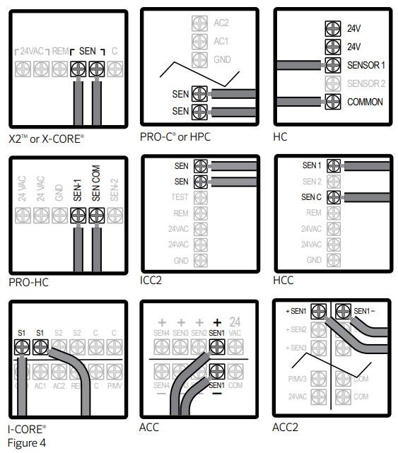
Wiring to Hunter Controllers
The Rain-Clik connects directly to the controller. This allows you to easily override the sensor by using the Sensor switch on the front panel.
- Remove the jumper from the two “SEN” terminals.
- Route the wires from the rain sensor up through the same conduit opening used for valve wiring.
- Connect one wire to the terminal labeled “SEN” and the other wire to the other “SEN” terminal (Figure 4).

Other Controllers - 24 Volt Solenoid Valves Only (No booster pump)
- With the two wires from the Rain-Clik at the controller, locate the “common ground” wire of the solenoid valves. If it is connected to the common terminal on the controller, disconnect it.
- Attach one wire of the Rain-Clik to the “common” terminal (usually marked “C”) on the controller.
- Attach the other wire of the Rain-Clik to the common wire leading to the valves.
Note: The common wire to the valves does not have to be interrupted at the controller. The Rain-Clik may be wired anywhere along the common wire line.

Other Controllers - 24 Volt Solenoid Valves with Booster Pump
- Locate the common wire to the solenoid valves and the common wire leading to the coil of the relay that starts the pump. If these two wires are connected to the “common” terminal on the controller, disconnect both of them.
- Twist together these two wires along with one wire from the Rain-Clik, and secure with a wire nut.
- Attach the other wire of the Rain-Clik to the “common” terminal on the controller.
Note: The pump circuit output must be 24 Volts in this situation. Do not proceed if 110V.
- Line-In
- Normall-Open Relay
- Line-Out (to Pump)
- Common Wire to All Valves
- Solenoid Valves

Hunter SRC (Discontinued)
The Rain-Clik connects directly to the SRC. This allows you to easily override the sensor by using the RUN (BYPASS SENSOR) position on the dial.
- Route the wires from the Rain-Clik up through the same opening used for valve wiring.
- Connect one wire to the RS terminal and other to the C terminal.
- Connect the valve common to the RS terminal.

Still need help? We're here.
Tell us what you need support with and we'll find the best solution for you.