Wireless Mini-Clik Sensor
- Manual Test Spindle: Press and hold the manual test spindle to confirm the proper operation of your sensor.
- Vent Cap and Spindle: Used to adjust reset rate or dry out time for the sensor.
- Radio Antenna: Transmits a wireless signal to the receiver up to 800' (243 m) line of sight. The antenna should be oriented vertically.
- Mounting Arm: Metal extension arm for mounting the sensor.
- Battery Status LED: Used to determine the status of the sealed battery. Pushing the manual test spindle will flash the LED light indicating that the battery is good.

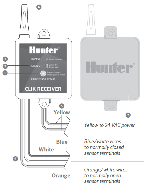
Wireless Receiver
- Bypass Button: Allows automatic or manual watering when the sensor is active.
- Receiver Status LED: Used to indicate the status of the sensor.
- Receiver Bypass LED: Indicates when sensor has been bypassed.
- Radio Antenna: Receives a wireless signal from the transmitter up to 800' (243 m) line of sight. The antenna should be oriented vertically.
- AC Power Wires: The two yellow wires are attached to a 24 VAC source from the controller.
- Receiver Wires: The sensor wires are attached to either the sensor terminals in the controller or in-line with the valve common wire.
- Blue/White Wires: Used for normally closed sensor applications (Hunter controllers).
- Orange/White Wires: Used for normally open sensor applications.
- Rubber Cover: Used to protect the receiver when mounted in outdoor locations.
Still need help? We're here.
Tell us what you need support with and we'll find the best solution for you.