It is the responsibility of the Contractor to ground all electrical equipment installed in relation to the irrigation control system. Grounding components will include, but not be limited to, the items described in the following paragraphs. Use grounding electrodes that are UL listed or manufactured to meet the minimum requirements of the US National Electrical Code (NEC).
Controllers
At the very minimum, the grounding circuit for controllers will include a copper clad steel ground rod, a copper ground plate and 100 pounds/45 kg of PowerSet® earth contact material, as defined below and per the following detail.
Ground rods are to have a minimum diameter of 5/8"/1.5 cm and a minimum length of 10 ft/3 m. These are to be driven into the ground in a vertical position or an oblique angle not to exceed 45 degrees at a location 8 to 10 ft/2.4 to 3 m from the electronic equipment or the wires and cables connected to it, and at right angles to the two-wire path. It is to be stamped as UL listed.
The copper grounding plate assemblies must meet the minimum requirements of section 250 of the NEC. They are to be made of a copper alloy intended for grounding applications and will have minimum dimensions of 4" x 96" x 0.0625" (100 mm x 1.2 m x 1.58 mm). A 25-foot (8 m) continuous length (no splices allowed unless using exothermic welding process) of 6 AWG solid bare copper wire is to be attached to the plate using an approved welding process. The wires are to be installed in as straight a line as possible, and if it is necessary to make a turn or a bend it shall be done in a sweeping curve with a minimum radius of 8" and a minimum included angle of 90°. Mechanical clamps shall be permitted temporarily during the resistance test process, but shall be replaced with Cadweld "One-Shot" kits immediately thereafter. The ground plate is to be installed to a minimum depth of 30"/75 cm, or below the frost line if it is lower than 30"/75 cm at a location 15 to 20 feet/4.5 to 6 m from the ground rod, electronic equipment and wires and cables. Two 50-pound/22 kg bags of earth contact material must be spread so that it surrounds the copper plate evenly along its length within a 6"/15 cm wide trench. The use of salts, fertilizers and other chemicals are not to be used to improve soil conductivity because these materials are corrosive and will cause the copper electrodes to erode and become less effective with time.
Install all grounding circuit components in straight lines. When it is necessary to make bends, do not make sharp turns. To prevent the electrode-discharged energy from re-entering the underground wires and cables, all electrodes shall be installed away from said wires and cables. The spacing between any two electrodes shall be 15 to 20 feet/4.5 to 6 m, so that they don’t compete for the same soil.
The earth-to-ground resistance of this circuit is to be measured, and the reading is to be no more than 10 ohms. If the resistance is more than 10 ohms, then additional ground plates and earth contact material are to be installed in the direction of an irrigated area. It is required that the soil surrounding copper electrodes be kept at a minimum moisture level of 15% at all times by dedicating an irrigation station at each controller location.
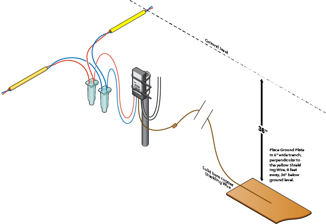
Decoder Grounding
At the very minimum, the grounding circuit for a decoder will include a copper ground plate and may also include 50 pounds/22 kg of earth contact material, as defined below and per the following detail.
The copper grounding plate assemblies must meet the minimum requirements of section 250 of the NEC. They are to be made of a copper alloy intended for grounding applications and will have minimum dimensions of 4" x 36" x 0.0625" (100 mm x 1.2 m x 1.58 mm). A 10-foot/3 m continuous length (no splices allowed unless using exothermic welding process) of 10 AWG/5 mm2 solid bare copper wire is to be attached to the plate using an approved welding process. This wire is to be connected to the decoder’s ground wire and 10 AWG/5 mm2 bare copper "shielding wire" as shown in wiring details. A 50-pound/22 kg bag of earth contact material must be spread so that it surrounds the copper plate evenly along its length within a 6"/15 cm wide trench per detail below. Salts, fertilizers and other chemicals are not to be used in an attempt to improve soil conductivity because these materials are corrosive and will cause the copper conductors and electrodes to erode and become less effective with time.
Install all grounding circuit components in straight lines. When it is necessary to make bends, do not make sharp turns. To prevent the electrode-discharged energy from re-entering the underground cables, all electrodes shall be installed 6 to 8 feet/2 to 2.5 m away from said cables, and at right angles to the two-wire path. If more than one electrode is used to achieve lower resistance, the spacing between any two electrodes shall be 15 to 20 feet/4.5 to 6 m, so that they don’t compete for the same soil.
The earth-to-ground resistance of this circuit is to be no more than 10 ohms. If the resistance is more than 10 ohms, then additional ground plates and earth contact material are to be installed in the direction of an irrigated area. It is required that the soil surrounding copper electrodes be kept at a minimum moisture level of 15% at all times by dedicating an irrigation station at each controller location.
Still need help? We're here.
Tell us what you need support with and we'll find the best solution for you.