Irrigation systems utilize a 24VAC electronic signal to initialize a valve's solenoid. Even though the system is low voltage, it is still always recommended a trained professional perform these tests.
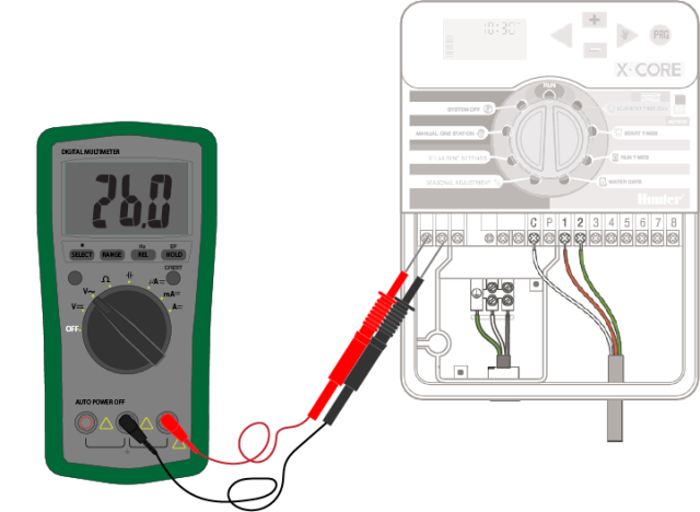
Using the AC voltage reading on your voltmeter, touch one probe to the station terminal you wish to test and the other probe to the C or COM terminal while the station is activated. Typically it does not matter which of the two colored probes goes where, but for consistency, purposes use the black probe for the C terminal and the red probe for the station terminal.
With the station activated and this icon showing; ( ![]() ).
).
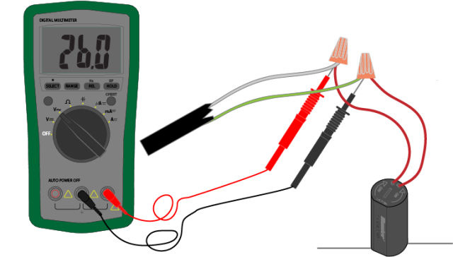
Use the same AC voltage reading on your voltmeter as used on the controller. It is no coincidence that the solenoid has two wires and the controller had two screw terminals for you to test.
Solenoids have two wires, one for the COMMON wire and one for the station's power wire. Typically COMMON wires are shared throughout irrigation systems to save on wire.
Place either probe from the voltmeter on what's presumably the COMMON wire at the valve manifold, place the other probe on the solenoids power wire. With the station activated you should have 24-28VAC.
Still need help? We're here.
Tell us what you need support with and we'll find the best solution for you.