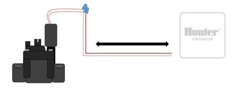
Installation of the X2 should only be done by trained personnel. Please refer to the example and instructions below for connecting the controller to the valve.
- Route valve wires between the control valve location and controller.
- At valves, attach a common wire to either solenoid wire on all valves. This is most commonly a white-colored wire. Attach a separate control wire to the remaining wire of each valve. All wire connections should be done using waterproof connectors.
- Secure the white valve common wire to the C (Common) screw on the terminal strip. Attach each of the individual valve control wires to the appropriate station terminals and tighten their screws.
- The transformer wires are already connected to the AC terminals so all that is required is to connect the primary power outlet for the plug.
NOTE: The MV terminal is only to be used if a master valve is on the system. Learn more

Wire Distance
| Valve Wire Sizing (Maximum One-Way Distance in Feet Between Controller and Valve) | |||||||
|---|---|---|---|---|---|---|---|
| Ground Wire Size | Control Wire (ft) | ||||||
Below is a chart indicating the maximum wire runs that can be used when installing Hunter AC solenoids and valves. | |||||||
18 AWG | 16 AWG | 14 AWG | 12 AWG | 10 AWG | 8 AWG | 6 AWG | |
18 AWG | 850 | 1040 | 1210 | 1350 | 1460 | 1540 | 1590 |
16 AWG | 1040 | 1340 | 1650 | 1920 | 2150 | 2330 | 2440 |
14 AWG | 1210 | 1650 | 2150 | 2630 | 3080 | 3450 | 3700 |
12 AWG | 1350 | 1920 | 2630 | 3390 | 4170 | 4880 | 5400 |
10 AWG | 1460 | 2150 | 3080 | 4170 | 5400 | 6670 | 7690 |
8 AWG | 1540 | 2330 | 3450 | 4880 | 6670 | 8700 | 10530 |
6 AWG | 1590 | 2440 | 3700 | 5400 | 7690 | 10530 | 13330 |
¿Aún necesita ayuda? Estamos aquí.
Díganos en qué necesita ayuda y encontraremos la mejor solución para usted.