WARNING! Flow-Sync is only designed for low-voltage connection to approved irrigation controller flow terminals. do not install in high-voltage 110V or 230V circuits.
Flow-Sync has two wire leads for the controller connection. These may be extended up to 1000 ft/300 m from the controller with direct burial- rated 18 AWG (1 mm) wires. Flow-Sync may also be used with Hunter ICD-SEN sensor decoders.
Proper irrigation system design and operation assures optimum performance of the Flow-Sync in monitoring for potential high flow conditions. Flow-Sync is primarily designed to shut off the irrigation system in the event of a catastrophic system failure such as a main line or lateral line break. However, depending upon the design of the irrigation system, the Flow-Sync can offer increased protection when components such as sprays or rotors are damaged or removed due to vandalism. The following may be helpful in making your Flow-Sync System operate at its optimum level.
The red and black lead wires from the Flow-Sync Sensor are for DC voltage. The red wire is positive (+) and the black wire is negative (-). When extending the wires to reach the controller flow sensor connection, the red and black wire polarity must be observed. Use an extension wire that has a similar color code.
- Connect the red lead from the sensor to the red (+) flow terminal in the controller.
- Connect the black lead from the sensor to the black (-) terminal in the controller. Use only quality waterproof connectors for all wire connections
- In the ACC controller, the terminals are marked “Flow”, one for red and one for black.
- In the I-Core controller, the terminals are marked either S1 (one is red, and one is black) or S2 (or S3 in metal versions).
Note: The Flow-Sync Sensor can be installed up to a maximum of 1,000 ft/300 m from the controller when installed with 18 AWG or 1 mm gauge or larger copper wire.
- When used with a Hunter ICD-SEN sensor decoder (ACC Systems only), see resource document below.
- Flow-Sync may only be used on Port A of a sensor decoder.
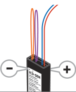
- Cut the purple loop (Port A) on the sensor decoder.
- Observe polarity-when the loop is cut, the lead on the station label side of the ICD-SEN is the negative (-) side.
- Connect the black wire from Flow-Sync to the negative side of the decoder port, and connect the red wire to the positive side of the port.
- Finish configuration as described in the ICD-SEN and ACC controller documentation.
ACC 1 - ICD-SEN Flow Sensor Programming
- Insert the sensor decoder into the programming port.
- Turn the dial into the "advanced features" position.
- Using the "down" arrow button, select "decoder functions".
- Select "program a decoder".
- Using the "+" button, adddress the decoder.
- The address can be 1,2,3,4, and 5 these are separate addresses.
- Push the "program" to buttom the address to the decoder.
- Turn the dial into the "run" position.
- Push and hold down the "information" button while you turn the dial into the "set flow monitoring" position.
- Using the "down" arrow button, select "select flow sensor".
- Using the "down" arrow button, select "location".
- Using the "+" button, change the location to ADM.
- Turn the dial back into the "advanced feature" position.
- Select "decoder dunctions"
- Select "Sen/dec setup"
- Using the "+" button enter the address of the following decoder port "A" will automatically display
Still need help? We're here.
Tell us what you need support with and we'll find the best solution for you.