The ACC2 controller allows up to six Pump and/or Master Valve outputs to be assigned in the controller. This applies to the decoder and conventional models. In this article, the following topics are covered:

The Pump/Master valve connections are located on the upper left-hand side of the Power Module.
- Locate the P/MV1, P/MV2, and P/MV3 screw terminals on the Power Module. These outputs are designed to supply 24 VAC, 0.8 A max, for a single Master Valve solenoid, or a Pump Start Relay (or Relay Booster).
- The return wire from each P/MV device (solenoid or relay) must be connected to one of the COM terminals on the lower part of the Power Module.
- Connect one output wire from each Pump relay or Master Valve solenoid to the desired 24 VAC P/MV terminal.
- Connect the return wire to one of the terminals marked COM to the right of the P/MV outputs.

P/MV OUTPUT: This output determines which P/MV terminal on the Power Supply Board will be used. P/MV outputs 4, 5, and 6 can be assigned to regular station outputs. The default for these outputs is DISABLED. See Soft P/MV (Outputs 4-6) further down this page.
P/MV LOCATION (Decoder Model Only): The Pump or Master Valve can be used on the two-wire path with an ICD-100 decoder or hardwired to the power module like a conventional version.
P/MV STYLE: Each P/MV will be selected as a default NORMALLY CLOSED operation. This is a station level setting, meaning the P/MV is activated by stations when they begin the cycle. The STATION SETUP menu allows you to set each station for the P/MV outputs it needs to run water. NORMALLY OPEN may also be selected and is discussed further in the Flow Operations section. Normally Open is not a station level setting. The valve is always open until a problem is detected at the Flow Zone, or MainSafe level when the controller activates the normally-open P/MV to shut the water off. Ability to schedule Normally Open P/MVs to be exercised for 1 minute based on an interval schedule and time.
P/MV OFF DELAY: This sets how long the P/MV output will remain active after a station stops calling for it (for example, during Delay Between Stations). It is preset to 15 seconds but can be changed (use caution) up to 60 seconds. Hunter is not responsible for damage to pump components when longer delays are set.
P/MV DIAGNOSTICS: The P/MV Diagnostics screen is to view the status and current draw of each active P/MV output. P/MVs that are not running are not shown.

- Press the lower right soft key to view the MAIN MENU.
- Turn the scroll wheel to the right to view the DEVICES screen.
- Press the scroll wheel twice to view the P/MV setup screen.
- Press the scroll wheel once and select a P/MV OUTPUT # between 1-3.
- P/MV outputs 1 through 3 always refer to the output terminals on the Power Supply Board.
- P/MV outputs 4, 5, and 6 can be assigned to regular station outputs. Learn More
- Turn the scroll wheel to the right and select the STYLE, Normally Closed or Normally Open. Push scroll wheel to select.
- Turn the scroll wheel to the right and select the DELAY if desired (3-60 seconds). Push scroll wheel to select.
- The stations for this Pump or Master valve need to be assigned to the appropriate stations. Select the soft key on the right for P/MV DIAGNOSTICS.
- Select the soft key for STATION SETUP.
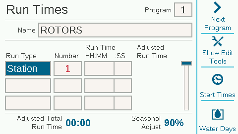
- Using the scroll wheel, select the station to assign the Pump or Master valve. Check the appropriate box for STATION P/MV USAGE.
- To make it easy for you to assign multiple stations, we have the COPY/PASTE feature. Press the soft key on the right for COPY, then toggle to next station pressing the top soft key NEXT STATION. Press the lower soft key for PASTE, then repeat the press for any additional stations needed for this P/MV circuit.

Prior to programming a Pump or Master Valve decoder in the controller, it should be assigned an output number. Learn more
- Press the lower right soft key to view the MAIN MENU.
- Turn the scroll wheel to the right to view the DEVICES screen.
- Press the scroll wheel twice to view the P/MV setup screen.
- Press the scroll wheel once and select a P/MV OUTPUT # between 1-3.
- Next, select a P/MV LOCATION. This can be set to the controller (if hardwired) or Decoder Module #1, #2, 0r #3.
- P/MV outputs 1 through 3 always refer to the output terminals on the Power Supply Board.
- P/MV outputs 4, 5, and 6 can be assigned to regular station outputs. Learn More
- Turn the scroll wheel to the right and select the STYLE, Normally Closed or Normally Open. Push scroll wheel to select.
- Turn the scroll wheel to the right and select the DELAY if desired (3-60 seconds). Push scroll wheel to select.
- The stations for this Pump or Master valve need to be assigned to the appropriate stations. Select the soft key on the right for P/MV DIAGNOSTICS.
- Select the soft key for STATION SETUP.
- Using the scroll wheel, select the station to assign the Pump or Master valve. Check the appropriate box for STATION P/MV USAGE.
- To make it easy for you to assign multiple stations, we have the COPY/PASTE feature. Press the soft key on the right for COPY, then toggle to next station pressing the top soft key NEXT STATION. Press the lower soft key for PASTE, then repeat the press for any additional stations needed for this P/MV circuit.

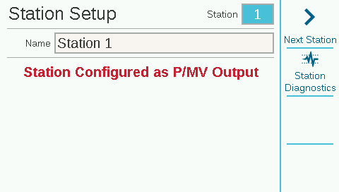
P/MV outputs 4 through 6 will show as DISABLED by default unless you select one of the station outputs to be used as an additional P/MV. These are called SOFT MV's. Once a station is designated as a P/MV, that is its only function. This should NOT be included in irrigation programs as a regular station. If this is included in the programming, the station number will appear in RED and be removed after you change screens.
- Press the lower right soft key to view the MAIN MENU.
- Turn the scroll wheel to the right to view the DEVICES screen.
- Press the scroll wheel twice to view the P/MV setup screen.
- Press the scroll wheel once and select a P/MV OUTPUT # between 4-6. All three outputs will appear as DISABLED until a station is selected.
- Scroll to select a STATION to be assigned as a P/MV.
- Turn the scroll wheel to the right and select the STYLE, Normally Closed or Normally Open. Push scroll wheel to select.
- Turn the scroll wheel to the right and select the DELAY if desired (3-60 seconds). Push scroll wheel to select.
- The stations for this Pump or Master valve need to be assigned to the appropriate stations. Select the soft key on the right for P/MV DIAGNOSTICS.
- Select the soft key for STATION SETUP.
- Using the scroll wheel, select the station to assign the Pump or Master valve. Check the appropriate box for STATION P/MV USAGE.
- To make it easy for you to assign multiple stations, we have the COPY/PASTE feature. Press the soft key on the right for COPY, then toggle to next station pressing the top soft key NEXT STATION. Press the lower soft key for PASTE, then repeat the press for any additional stations needed for this P/MV circuit.
Still need help? We're here.
Tell us what you need support with and we'll find the best solution for you.